Theory of Application: The Safe Drones
- Jan 27, 2017
- 6 min read
ACCELEROMETER

Model of accelerometer
The diagram below shows the model of an imaginary square and ball which depicts the working mechanisms of an accelerometer. Because a tilt in any object will result in an imbalance in its acceleration components, it means that as we can take the imbalance values to calculate the angle at which the sensor is at.
Typical readings from an accelerometer would give its sensor readings in g’s. Using the vector formula below, we can calculate the amount of g-force acting on the sensor:

Vector magnitude formula
With 1g representing 1 unit of force acting on an object, and with 3 axes from the sensor, the magnitude of the values in g at rest will always be equal to the acceleration experienced by the sensor, with that being on Earth.

Angle to acceleration conversion
When in free fall, the imaginary ball does not act on any sides of the wall because it is traveling at terminal velocity. The resultant acceleration will be zero because the object is accelerating at the same speed of the force acting on it (ie. gravity) and the resultant forces are cancelled out. At this stage, the magnitude of the forces is 0g. In the program, we set the condition of free fall at 0.2g, a value that is almost never reached by the drone unless it is falling from the sky. It also decreased the reaction time of the parachute.

Model of accelerometer in free-fall

Right-angle triangle for tilt calculation
Tilts can be measured by isolating an axis from the 3 axes to obtain two axes. A triangle like the one below will be obtained and the angle of tilt can be calculated by a simple trigonometry formula:
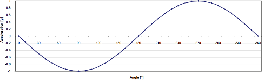
Graph correlating acceleration and g-values
Eventually an inverse sine graph can be plotted for the acceleration against the angle and can be compared for all angles.
Barometer
The barometer works by sensing and observing the surrounding air pressure. The MPL3115A2 reports its readings in Pascal (Pa) but the more commonly used unit by weather sources are in hectopascal (hPa). In the code, we divide the values given by 100. As a guide, the average pressure at sea-level is 1013.25hPa and as the altitude increases, air gets thinner when compared to sea level. From the graph below, it shows that there is a linear correlation between the air pressure and height from sea level to 5 -10km in the air which is means the sensor will be more accurate at these ranges.
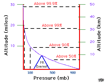
Pressure varying with height
The barometer senses the air pressure and sends it back to the Arduino board. But its readings will not be as accurate as an accelerometer in detecting free-fall but good enough for an approximate height detection which is sufficient to prevent the drone from flying up too high into the crowded airspace of Singapore with traffic from commercial, private and military planes.
The parachute will be activated when the drone reaches an altitude of 200ft (61m) which is the altitude regulation set by CAAS. As the height of 60m is relatively high and most drone pilots will never achieve that height, it is relatively safe to use a barometer because even an error of 10% would already mean the drone pilot has gone too high and the difference will be unnoticeable by the human eye at from ground level.
The MPL3115A2 has a typical altitude resolution variance of 0.3m which was good enough for obtaining an accurate altitude when the drone was in the air. This resolution is much better than the in-built resolution in the Pixhawk which gives an error of up to 9% and registers more noise.

MPL3115A2 breakout barometer/accelerometer
Programming
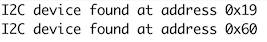
The sensors have to ability to run using the I2C protocol, which allowed us to link up both sensors seamlessly to the same port on the Arduino which made wiring much easier compared to using different protocols. A sensor utilizing the protocol only requires 4 pins to send signals and the addition of other sensors will not deplete the number of ports uses as they can be daisy chained. The pins required are 2 power lines (3.3V and GND in this case) and the SDA (Data Signal) and SCL (Clock Signal) pins. Multiple devices can be stacked on the same pins as long as they have different addresses. To check the addresses and viability of using multiple I2C devices on the same pins, an I2C scanner was used. Below shows the code used for the I2C scanner:
#include <Wire.h>
void setup()
{
Wire.begin();
Serial.begin(9600);
}
void loop()
{
byte error, address;
int nDevices;
nDevices = 0;
for(address = 1; address < 127; address++ )
{
Wire.beginTransmission(address);
error = Wire.endTransmission();
if (error == 0)
{
Serial.print("I2C device found at address 0x");
if (address<16)
Serial.print("0");
Serial.println(address,HEX);
nDevices++;
}
else if (error==4)
{
Serial.print("Unknow error at address 0x");
if (address<16)
Serial.print("0");
Serial.println(address,HEX);
}
}
if (nDevices == 0)
Serial.println("No I2C devices found\n");
delay(5000); // wait 5 seconds for next scan
}
I2C addresses

Formula to convert Pascal pressure to alitmeter setting
The code scans for all available devices connected to the pins and once detected, uses the return value to check if the device acknowledges the address and then sends it to the serial monitor for us to check the address. The serial monitor then displays the addresses of the sensors:

Serial monitor output when 61m is reached
On the Arduino Uno and other Arduinos using the ATmega328 microcontroller chip, the SDA and SCL pins are attached to the A4 and A5 pins on the board. This meant we had the options of using the Arduino Uno or Nano in terms of model choice and we decided to use the Nano because of its small form factor. Much of the complicated mathematical calculations were done in the background with the calculations for the conversion of the pressure sensor to an altimeter being done in the background as well. The difference between the two modes is that the pressure sensor is able to detect a large range of pressure and force to be displayed. The altimeter mode provides a more accurate reading from the sensors to be converted to distance (height).
The program identifies the tilt angles of the drone and the height limit of the drone and automatically cuts the power off and deploys the parachute to allow the drone to not cause harm to others and safely return it to the ground safely. To summarize the code, the program is split up into a few functions that allow troubleshooting to be carried out with greater ease. In the barometer() function, the program reads the altitude of the drone and sends a warning signal when the drone passes the 50m mark and sends an activation signal to the main code when the height of 61m has been reached. In the accelerometer() function, the tilt angles are converted from g-forces and free-fall is detected as well. If any of the conditions are met, the function sends back an activation signal to the main code. Similarly, if the radio frequency rfReceiver() function receives the encrypted key from the transmitter when the operator decides to manually deploy the parachute, the function sends back an activation signal to the main code.

Excerpt of main code
When the main code receives a positive activation signal, it then activates the parachute in a separate function.
Because of known clock errors when running the libraries, VirtualWire.h and Servo.h, we were unable to place the codes together and another Arduino Nano had to be used to resolve the problems. The external Arduino will be dedicated to receiving an encrypted code on the 315Mhz radio frequency band and will send a send output to the main Arduino which is used to process the two sensors and to activate the parachute.
Power Relay
When the parachute is to be deployed, the propellers of the drone will still spin on many instances. It is important to cut the power off to the drone to prevent propeller entanglement and inefficient deployment of the parachute. We decided to use a power relay (SONGLE SRD-05VDC-SL-C) for the control of power on the drone. When the activation status is HIGH on the Arduino, the power of the drone will cut for a while to allow the deployment of the parachute before allowing the drone to reconnect to the RF transmitter.

Songle Power Relay
The input pins of the relay will be attached to a digital output of the Arduino while the output will be connected to the normally closed pins on the relay. When the signal is sent, the power relay will temporarily cut and be restored as per the code


Comments